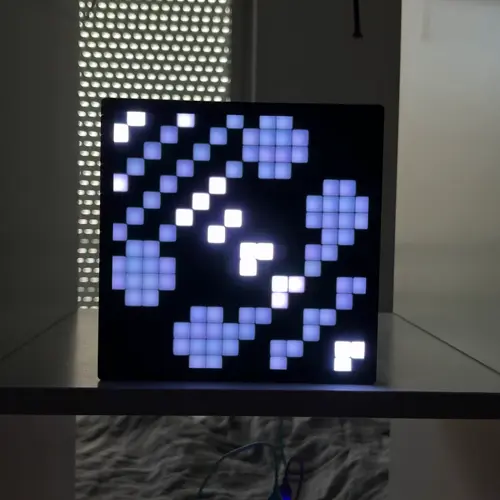
A few months ago I made a 16×16 WS2812B LED grid in an enclosure with a plastic diffuser, a cool project I found on Thingiverse. It looked great and vibrant and I just didn’t know what exactly I could do with it. Inspiration struck when I figured out the logo I’ve made for my very own damn website was actually 16×16 pixel art. It took a couple of months but I put 2 and 2 together. So, here is my own logo in a cool pulsing light installation!
Parts
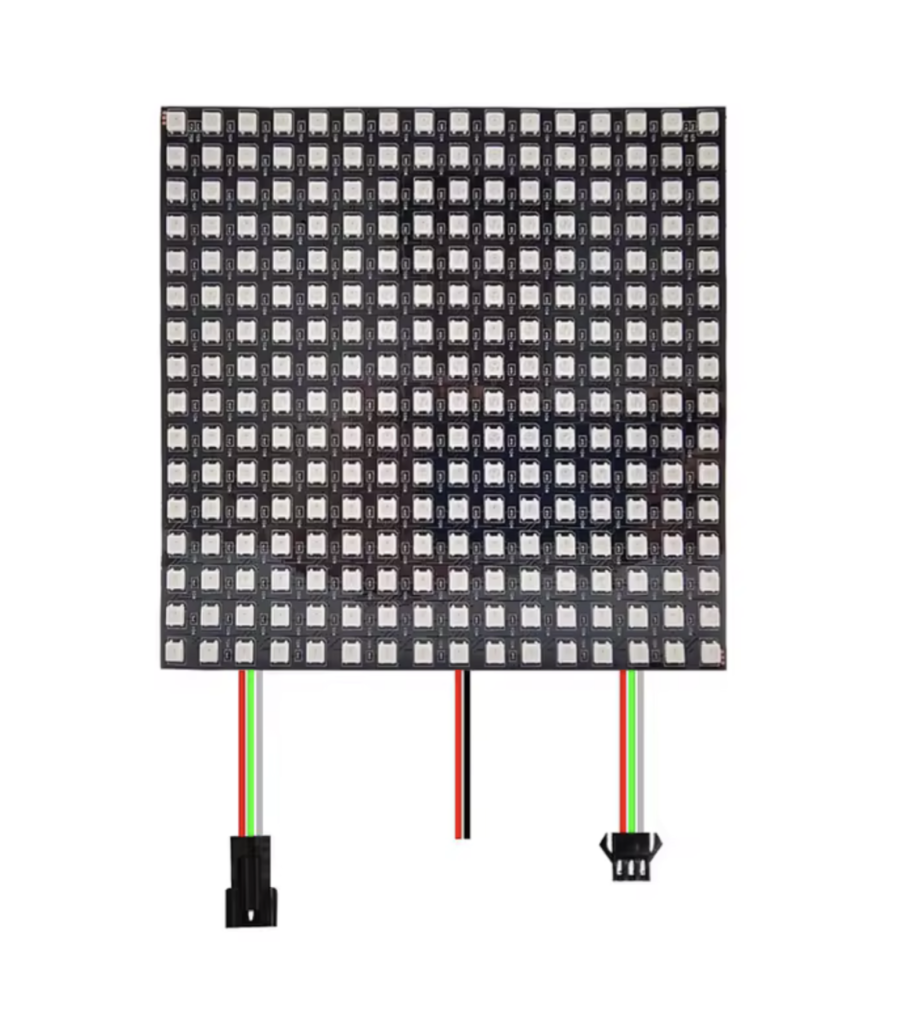
The WS2812B LED grid is a simple device which chains many of these RGB LEDs in a serpentine chain. Keep that in mind when writing code! Also it’s important to lower the maximum brightness quite a bit as full brightness will draw way too much current.
It was really hard finding a black transparent plastic diffuser locally so I just committed and got the one from Adafruit which they have specifically for projects like this. After getting it cut to size, it fit perfectly and everything came together.
The microcontroller running this whole thing is Soldered’s good ole’ Dasduino CONNECTPLUS, a board I’ve made many projects with.
Code
The code is a simple Arduino sketch which contains my logo in a literal ‘bit map’ (ha ha) and lights up the LEDs which are marked as ‘1’:
const uint16_t LOGO[HEIGHT] = {
  0b0100100101100000, // row 0
  0b1001001011110000, // row 1
  0b0010010011110000, // row 2
  0b0100100101100000, // row 3
  0b1001001000000110, // row 4
  0b0010010000001111, // row 5
  0b0100100100001111, // row 6
  0b1001001000000110, // row 7
  0b0110000011001100, // row 8
  0b1111000010001000, // row 9
  0b1111000000110011, // row 10
  0b0110000000100010, // row 11
  0b0000011011001100, // row 12
  0b0000111110001000, // row 13
  0b0000111100110011, // row 14
  0b0000011000100010  // row 15
};If you look at an angle, you can actually kind of see the logo in the code! Very cool.
WS2812B matrices are wired in a serpentine pattern: row 0 runs left to right, row 1 right to left, and so on. Without accounting for this, every odd row would appear mirrored. A small helper fixes that:
uint16_t xyToIndex(uint8_t x, uint8_t y) {
  if (y & 1) {
    return y * WIDTH + (WIDTH - 1 - x);  // odd rows: reverse x
  }
  return y * WIDTH + x;
}
I’ve also implemented the button IO0 to create a brightness pulsing animation from the centre. For each lit pixel, it calculates the radial distance from the grid’s center, then compares that against a slowly incrementing phase value to get per-pixel brightness:
int16_t delta = (int16_t)r - (int16_t)(wavePhase & 0xFF);
if (delta > 128) delta -= 256;
if (delta < -128) delta += 256;
int16_t bri = 255 - (abs(delta) * 255) / WAVE_WIDTH;Overall, very happy with how this turned out!